Tacho, tacho
Knowing what is going on with your engine is useful to know for diagnosis purposes as well as for how hard you can get away with pushing it on the track.
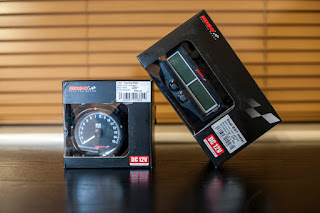
With the addition of these new Koso EGT, tacho and a pair of TTO cylinder head temperature gauges, I will be well in the know at all times!
*Spoiler*
By all means read this blog, it is interesting after all (I hope), but I wouldn't plan a build of your own based too closely on this bracket design. Maybe try this on.
Mounting
Much time was spent offering up different gauges in a variety of configurations to see what would work best, not only to look good, but to fit in the space I have available and present the information to me in a simple easy to read manner. All very important when buzzing round the track like a loon.
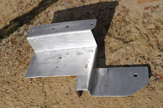
I decided early on that I wanted all of the gauge faces on the same level. This would be tricky as each gauge was of a different depth. I decided to try making a backing plate out of thin sheet aluminium which would be bent at different levels for each gauge.
I first mocked up a backing plate out of card which gave a rough idea of where everything would go and what sized sheet I would need. This was helpful although the flexibility of the card meant I wasn't 100% sure that all the bends were in the right place.


This also showed that the Tacho was sitting too deep into the panel. This was probably caused by the thicker bends in the card causing my panel to be too long.
The EGT gauge wouldn't fold flat either due to a fastener fowling the factory bracket which was disappointing.
That aside; rooting for the cables looked good and once I had a mounting idea I would be able to shape and tidy the bottom of the bracket.
First change was to take a dremel and needle files to the factory EGT gauge bracket.
Once I had the shape and clearance I wanted I went ahead and painted the disturbed area in gloss black.
Next up I tidied up the TTO gauge part of the bracket to give the tacho clearance and radius the corners. I also trimmed 4 mm from the top that I didn't need.
The bottom of the bracket was chamfered and reduced leaving a square bed at the bottom to mate with a piece of 20mm box section that I would be mounting this all to.
I took 16mm out of the depth of the Tacho's indent and chamfered its radius as you can see on the left. Soon after I realised the tacho mounting hole was now too far outboard so this was all lopped off.
Another test fit showed everything was looking okay so a bit of time with some sand paper later and I was ready to paint.
I was tempted to stick with raw ally but the bike was leaning towards a bit of a black theme so I didn't buck the trend.
I hung the bracket up in the sun with some old wire and gave it a base coat.
Followed by a couple of coats of black!
Wiring
 I picked up a 3 Amp hr 12v battery from screw fix. This was wedged into a gap in my frame and tie
 wrapped in place. Ideas of a tray were thought of and promptly dismissed as that would take an age. Another time maybe?
Next up: the wiring loom.
 I had already bought a micro toggle switch from Fry's; a large electronics store in Las Vegas. Which is a bit like a large Maplin crashed into Currys, rolled into a cafe, and finished up in PC worlds front window in the 80's. It sells lots of elecricery.
Back to the switch, I wired this in the positive line. This was terminated with a spade fitting to attach to the alarm battery and a similar wire was run for neutral. both of these wires had a tap off where I soldered in an Oxford products battery charging lead. These were then terminated at a joint connector for all of the appliances.
With the loom done; the switch was attached to the clock bracket I had made earlier and set aside for the next bit.
With the loom done; the switch was attached to the clock bracket I had made earlier and set aside for the next bit.
Welderering
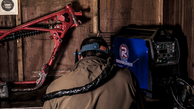
With a little playing with sheet metal and welding a nut to my headstock as experience; I was a long way from pro but it was welding time.
I cut some 20mm box section to size and filed a radius to match up to my front fairing bracket.
After a little offering up to find the best spot for it I stuck some tack welds on the corners.
Happy with my positioning I welded my way round till the box section was secuely glued to the fairing stay with metal.

As I was putting quite a bit more weight on the front of my bike than my currently brazed on front faiing bracket had been designed for; I decided to add a triangle of sheet steel to bulk it up.
I also stuck a ring of weld round the tube to improve the current brazing.
This was all later rubbed back and painted matt black like the rest of the frame.
All finished?
Everything bolted together nicely once finished and as you can see it looked pretty tidy.
Vibration is a continuous issue with the RD and on it's first race of the year, this bracket didn't fair well.
I had already removed the EGT gauge as I never got round to fitting the probes in the time I had.
I had already removed the EGT gauge as I never got round to fitting the probes in the time I had.
The tacho was off after the practice run due to it not working. It turns out that the Koso tacho does not work with a Femsa ignition. In fact very few tachometers do which I would end up tackling later. This was fortunate as on removal I spotted a crack running down the thin aluminium sheet. It wasn't up to the job it would seem.
The TTO gauges survived the race meet but by the end everything was looking rather tired.
A disappointment but a learning point no less.
Now back to the garage to make something a little stronger.


Comments
Post a Comment