Exhausting work
As things continuously vibrate themselves off my bike it was clearly time for my exhaust to drop off.
Which it did.

The plan
During my one and only full trip round Pembry race circuit in Wales my left exhaust bracket cracked through as you can see on the right. Thankfully my fairing caught the exhaust resulting in little damage and a functional machine so no major problems there.Now back home and post some discussion with Andy Green; I had decided to make new mounts that should survive a little better than what I had.
The straps on the pipes were something the previous owner had used and I had cobbled some sheet and rubber spacers together to marry them up to my frame.

The solution proposed to me was to use tubular engine mount bushings in some steel tube that would be welded to my frame.
The exhaust would then marry up to these bushes via some split box section . The box section would be welded to the pipe via a stress spreading sheet that would be welded on two sides to spread the load on the expansion chambers whilst also allowing for some flex and expansion.
This would be a test for my welding skills but if I was going to make my own pipes in the near future then I would benefit from the practice.
Did I mention I want to make some pipes? Lets see when I get round to that...
Get to work

I whipped the pipes off of the bike having had a good look at strap positioning locations first.
Out came the angle grinder and cutting discs; then off came the old exhaust straps.
I used an air grinder with a cutting then grinding disk to get back down to the clean pipe. A dremel was used for some fiddly bits but aside from some big lumps of weld this was fairly quick and easy.
Hiccup

During the clean up I spotted a large crack in the pipe across the front of the old strap.
It would appear that this was caused by the pipe being pulled up too high into the frame where it rubbed (a wear mark was evidence of this), putting a bending load between the frame and the bracket causing it to crack.
Taking the 'how' into consideration I went about fixing the symptom.
The pipe was cleaned thoroughly starting with a simple rub down followed by a wash and finishing with a localized spot clean with alcohol after the grinding back.
I stripped the effected area of paint with the grinder then used a grinding tip on a Dremel to rout out a channel along the crack.

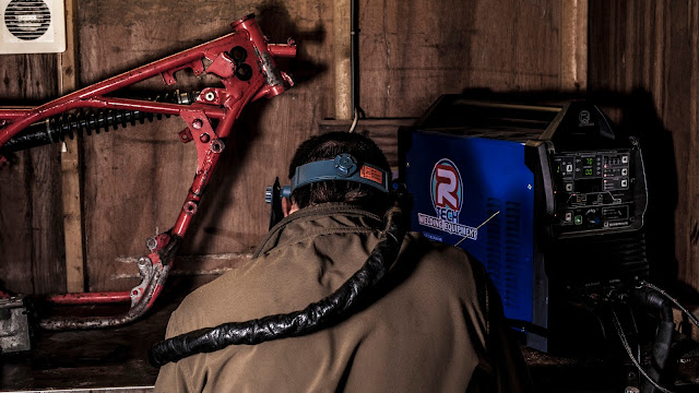
The Amperage was set to 35 maximum which I controlled with a foot pedal.
As positioning the exhaust was tricky without it falling over I was stuck welding towards myself which gets interesting as you move round the radius. The welds were ultimately functional however and so far I hadn't blown any irreparable holes in the pipe yet!

If I wasn't totally lazy I could have ground these welds flush but the next part would be largely on top of these repairs so I chose not to.
Bracing
 Now I needed some straps on the pipes. The design I was recommended uses split box section with some plate acting as a loads spreader brace.
I cut out near square rectangles of sheet steel.
The pipe itself was stripped of paint and contaminants in readyness for welding.
These were roughly shaped the a vice and hammer. Once the shape was getting close I slipped them onto the pipe and carefully worked them to the point where one edge could be tacked on.
With the sheet more firmly heald in place now I could work the sheet closer to the contours of the pipe.
Once things were pretty flush on the two edges that I wanted to weld, I ran a bead with the tig.
This time the Amperage was ramped up to 60 using the pedal for control. I rarely used peak power other than on top of old welds which needed a bit more to melt.
Both pipes were done in this manner and set aside.
Frame mounts.
The frame mounts were made using TZ250 engine bushes that slide into some tube that I machined out of some 30mm steel bar.
The steel tube was welded to an opportune location on the frame using a lot of build up. This ended up a bit of an uglier weld than I would have liked where, yet again, a mig would have been a lot easier.
Once everything was cool, I painted all of the exposed metal and once that was dry, popped in the frozen bushes on both sides.


The pipes were installed at the header end and held in place at the back using cargo straps.
This gave me the chance to line up where the exhaust straps would need to be welded on.
I had to take care not to have the pipes tucked up too tight this time as to cause stress and crack them again. On the same note though I didn't want the expansion chambers fowling the fairing either.
Once I was happy I took rough measurements and parked where I wanted things to go for future reference.

The straps themselves were made from some 30mm box section which was split and shaped as you see on the left.
For clearance reasons the left and right straps face the same way but were otherwise similar.
The hardest part of making these was profiling the bottoms to match (loosely) the shape of the pipe.

When things were looking close I drilled a 10mm hole in the top of each and bolted the straps in place.
With everything lined up it was a case of tacking them in place before removing the pipes entirely and running a weld round the bottom of each strap.
At some point I had managed to move one strap causing me to later adjust its shape but other than this all went well with some passable welding going on using the Tig guns trigger still set to 60 Amps.

Once both straps were on and everything had cooled down I threw some paint on to protect the exposed metal.
I didn't have any heat resistant paint handy so standard black gloss would have to do till I got some Although time would show that this end of the pipe would be cool enough to get away with it anyway. The pipes were hung up to dry over night.
The next day things were bolted up.
I ended up buying some new M10 bolts from Sleaford fasteners with a pain unthreaded area that covered the entire length of the spacer so the nut torqued down on the thread and not the spacer.
 In order to achieve this the bolts were very long and needed cutting
 down with an angle grinder and the threads tidied with a file.
The right side was straight forward but the left had some clearance issues with the drive chain. As such the spacer needs to be sticking out of the tube a bit so the nylock nut doesn't run on the chains rivets.
The spacers are prevented from falling out by a mixture of friction, the adjacent exhaust and the header spring. This way they can freely move within a limit so reducing stress yet not flapping about too much.
This arrangement seemed to work along with some wire locking providing insurance against any failure.
All was done in time for Mallory park CRMC and the pipes behaved themselve just fine.


Comments
Post a Comment